Wiring Diagram For Trailer Plug With Electric Brakes
But, it doesn’t imply link between the wires. The four wires control the turn signals, brake lights and taillights or running lights.

Trailer Plug Wiring Diagram With Electric Brakes Trailer
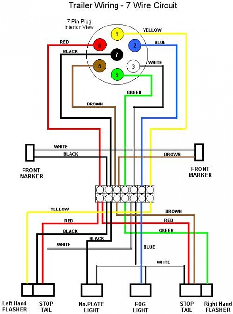
7 pin trailer wiring diagram with brakes it reveals the components of the circuit as simplified shapes and the power and signal connections in between the devices.

Wiring diagram for trailer plug with electric brakes. But, it doesn’t mean link between the cables. Wiring diagram trailer plugs and sockets. This wiring electric trailer brakes diagram model is more acceptable for sophisticated trailers and rvs.
Narva 7 and 12 pin trailer connectors comply with all relevant adrs. Wiring diagram for trailer lights with electric brakes from www.caretxdigital.com Injunction of 2 wires is generally indicated by black dot at the intersection of 2 lines.
10 7 pin trailer plug wiring diagram truck side truck diagram wiringg.this has now been replaced by 13 pin euro plugs on all new caravans. As the name implies, they use four wires to carry out the vital lighting functions. This wallpaper was uploaded at december 30, 2021 by tamble in trailer.
Wiring diagram trailer with brakes. If your vehicle is not equipped with a. Wiring diagram for a trailer with electric brakes from.
Injunction of two wires is usually indicated by black dot on the junction of 2 lines. Trailer wiring diagram with electric brakes wiring diagram is a free worksheet for you. Sometimes, the cables will cross.
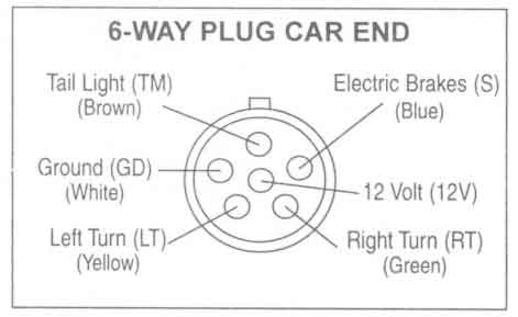
6 way plug wiring diagr am standard wiring* post purpose wire color tm park lights brown gd ground black (or white) s trailer brakes blue lt left turn/brake light yellow rt right turn/brake light green a accessory red the most common variances on this diagram will be the (blue/brake) & (red/acc.) wires will be inverted. Traditional trailer with brakes use a 5 pin connector. There will be primary lines which are represented by l1, l2, l3, and so on.
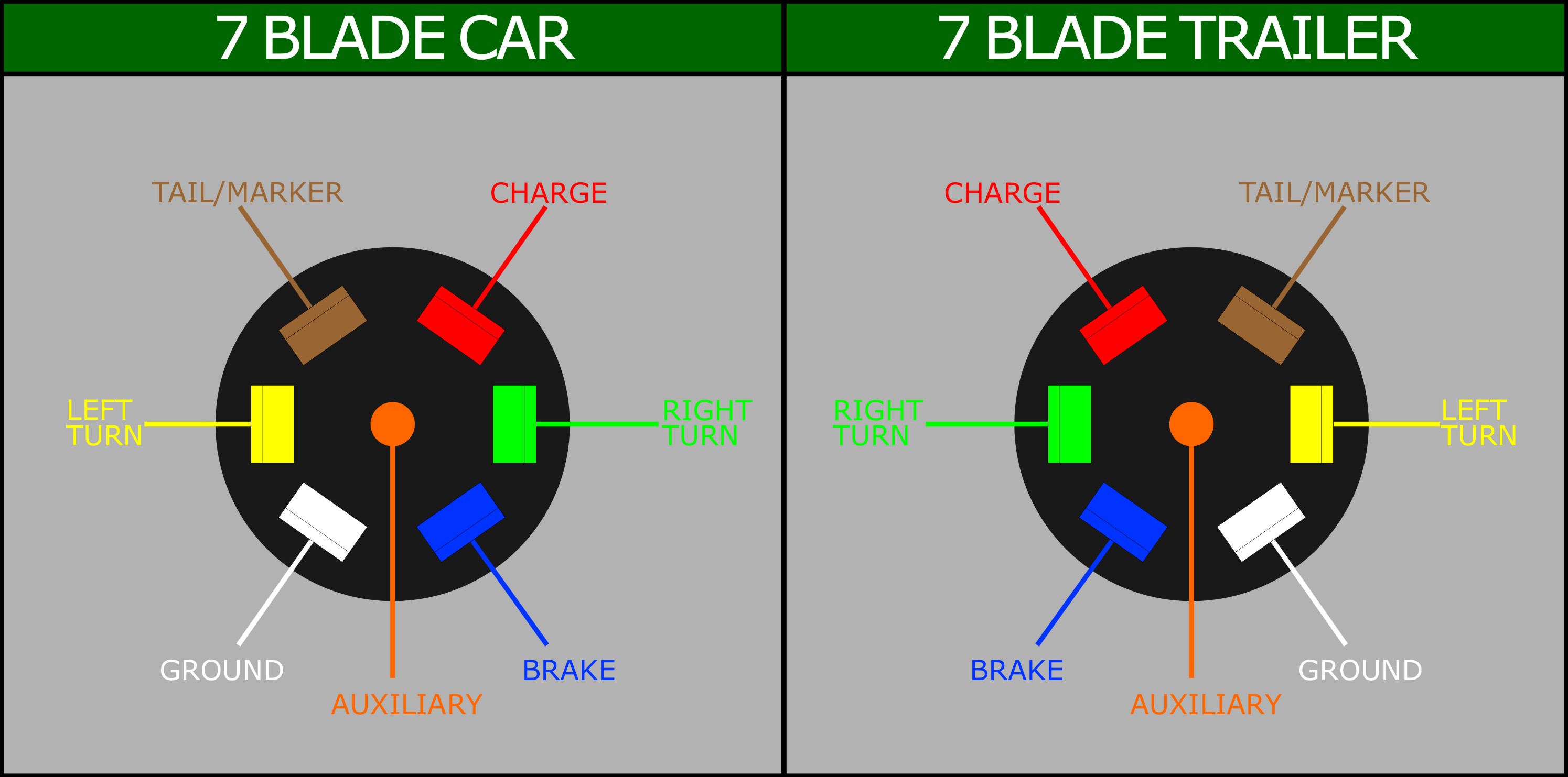
As stated earlier, the lines in a trailer wiring diagram with electric brakes signifies wires. 7 way plug wiring diagram standard wiring* post purpose wire color tm park light green (+) battery feed black rt right turn/brake light brown lt left turn/brake light red s trailer electric brakes blue gd ground white a accessory yellow this is the most common (standard) wiring scheme for rv plugs and the one used by major auto manufacturers today. T he brakes of a 4x4 are great until you slap an extra tonne or two on the back, which is why most states require any trailer that weighs more than 750kg to have its own braking system.
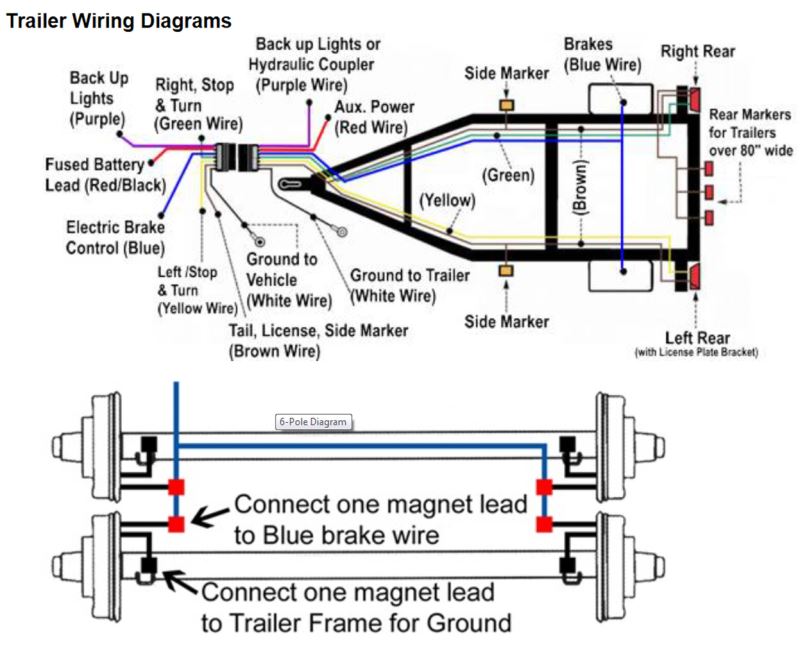
A wiring diagram is really a basic standard pictorial. Building tiny house on flatbed trailer and need brake controller and wiring for electric brakes trailer wiring diagram trailer light wiring flatbed trailer dexter trailer brakes […] Blue = electric brakes or hydraulic reverse disable (see blue wire notes below.) in the trailer wiring diagram and connector application chart below, use the first 5 pins, and ignore the rest.
In electric powered engineering, a 7 way trailer plug wiring diagram with electric brakes is normally utilized as being an example to clarify the electric circuits to people unfamiliar with electric technology. At times, the wires will cross. 7 way plug wiring diagram standard wiring post purpose wire color tm park light green battery feed black rt right turn brake light brown lt left turn brake light red s trailer electric brakes blue gd ground white a accessory yellow this is the most common standard wiring scheme for rv plugs.
7 way plug wiring diagram standard wiring post purpose wire color tm park light green battery feed black rt right turn brake light brown lt left turn brake. 7 pin flat trailer wiring diagram with brakes. How to wire up electric trailer brakes it still runs is a free worksheet for you.
A wiring diagram is actually a refined conventional pictorial. There will be principal lines which are represented by l1, l2, l3, and so on. They also provide a wire for a ground connection.
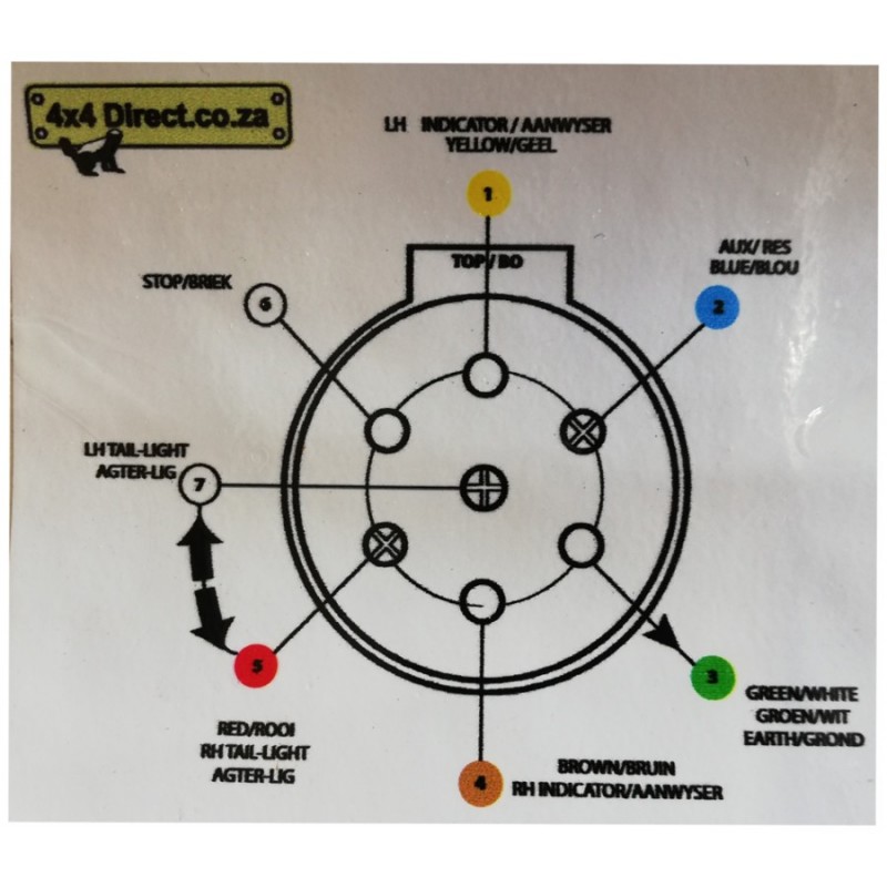
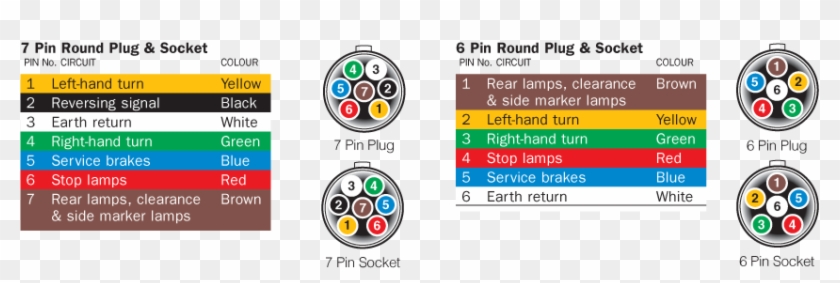
Below we have the wiring diagrams for both a 7 and 13 pin connector. Trailer plug 7 pin trailer wiring diagram with brakes. Electric trailer brake wiring diagram utilizes virtual wiring to signify bodily links within a method.
7 way plug wiring diagram standard wiring post purpose wire color tm park light green battery feed black rt right turn brake light brown lt left turn brake light red s trailer electric brakes blue gd ground white a accessory yellow this is the most common standard wiring scheme for rv plugs and the one used by major auto manufacturers today. This wallpaper was uploaded at december 30, 2021 by tamble in trailer. White wire provides ground for completion of the circuit.
As stated earlier, the lines in a 7 pin trailer wiring diagram with brakes signifies wires. Install all the cables of appropriate gauge, tucked with trailer frame in protective covering to ensure the proper functioning of electric brakes.

Trailer Plug Wiring Diagram With Electric Brakes Trailer
Instructions to Wire a Trailer for Electric Brakes

Universal Installation Kit for Trailer Brake Controller
trailer plug 7 pin wiring diagram australia IOT Wiring

Telecaster P90 Wiring Diagram

Wiring Diagram for Utility Trailer with Electric Brakes

Trailer Wiring Diagram Brakes Trailer Wiring Diagram
trailer 7 pin wiring diagram australia Wiring Diagram


Car Trailer Plug Wiring Diagram Australia Wiring Diagram
Wiring Diagram For Trailer Plug On Car Wiring Diagram Line

Telecaster P90 Wiring Diagram
2017 ford trailer plug wiring diagram Wiring Diagram

Telecaster P90 Wiring Diagram

Trailer 7 Way Plug Wiring Diagram Trailer Wiring Diagram
Car Trailer Plug Wiring Diagram Australia Wiring Diagram

Trailer Wiring Diagram With Brakes Simple Trailer Wiring
7 Pin Trailer Plug Wiring Diagram Australia Wiring Diagram
Wiring Diagram For Utility Trailer With Electric Brakes

4 Flat Trailer Plug Wiring Diagram Irish Connections